How I failed to build a game console. Part II
In my previous post, I started discussing a failed attempt to build a fantasy game console. Since I didn’t provide enough technical details on my design and why it failed, you can consider this to be a postmortem report (of some sort) on the effort. But solely classifying this as a postmortem makes it sound like the project is dead, and that's actually not the case. While writing these posts, I've had a lot of time to think through the issues I faced, and I've developed a few ideas on what my next steps in reviving this project could be.
For the first part of this post, I’ll discuss how I connected the display to the Raspberry Pi Pico. This will pretty much cover all the technical aspects of what I did. Then I’ll provide the code I wrote and describe some of the modifications I made to the hardware in hopes of achieving better performance.
In the concluding parts of the post, I’ll touch on why my attempt failed and share what my potential next step will be. Before we delve, I want to state that if you read this, and you come up with any ideas worth sharing, do not hesitate to hit me up.
Connecting the Display
The ILI9341 display provides two primary channels of communication: you can either go through one of its parallel interfaces (transmitting 8 through 18 bits at the same time), or you can use one of its two serial interfaces (with either 3 or 4 wires). For simplicity—and maybe for my own sanity—I went with the four wire serial interface.
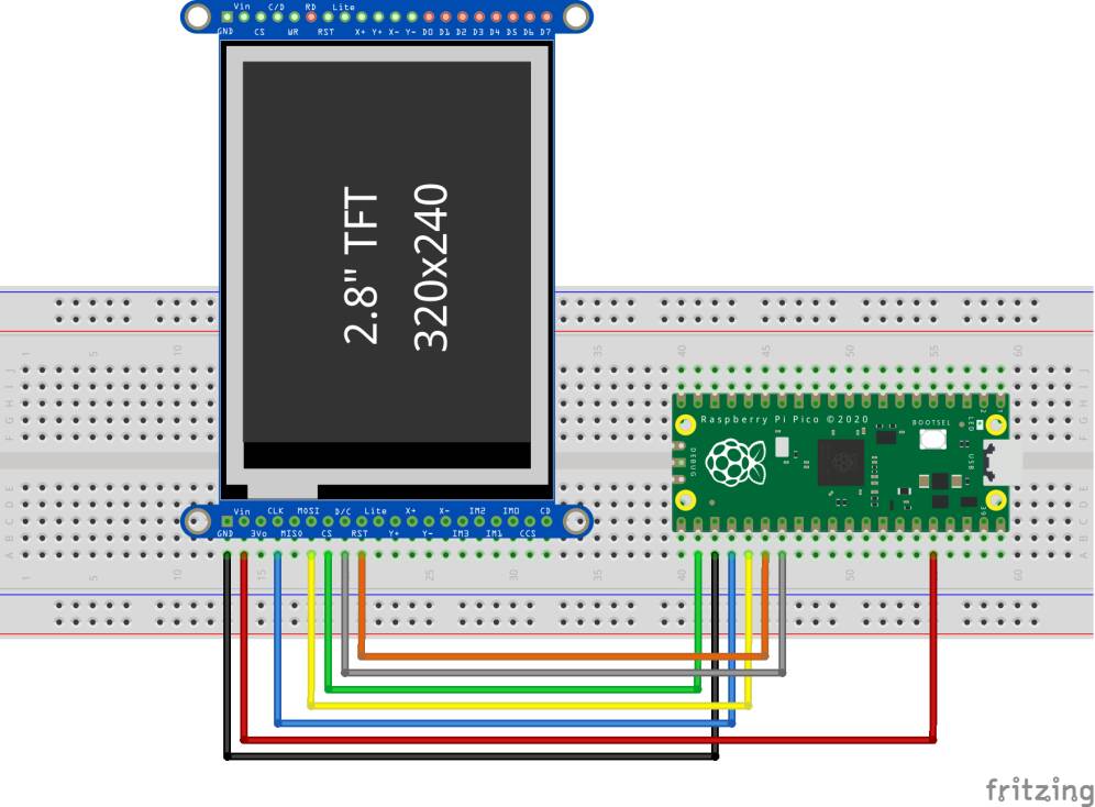
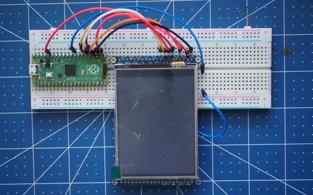
My steps for connecting the interface came from Adafruit’s excellent tutorial on the ILI9341. Although their tutorial was primarily targeted at folks using their feather family boards, the principles seemed to translate easily to the raspberry pi pico.
With a four pin SPI implementation I needed to connect the chip select (CS), clock (SCLK), transmit (Master Out Slave In or MOSI), and receive (Master In Slave Out) lines between the display's SPIO interface and the Pico's. Matching the CS and SCLK pins were pretty straight forward—both pins were identically labeled on both devices. Connecting the MOSI (Master Out Slave In) pin on the display and TX pin on the Pico was, however, a little hard to map out, since they both have different names, but I eventually got it after some reading. It was rather interesting how much of a while it took for me to figure out that the MISO (Master In Slave Out) and RX pins were not necessary for my use case—effectively making my implementation a three-wire one.
Sending data to the display
The ILI9341 is operated by commands sent through the SPI (or whatever chosen connection) interface. Each command is a byte long, and depending on the command, the byte could be followed by a variable number of other argument bytes.
Commands do a lot: they help display stuff by writing to the display's memory, they help in controlling the back light, and they can even help put the display to sleep for power management. But even with this extensive coverage of capabilities, the commands only provide low level access to the display's memory for drawing graphics.
Unfortunately, there are no internal routines for drawing primitives (like circles, rectangles, or other shapes) to the display, and there are equally no internal routines for manipulating bitmaps to do cool stuff stuff like rotation and scaling. All you get is raw access to the memory and you have to make good use of that. And that's actually good by design.
Fortunately, though, several libraries (like Adafruit's GFX and LVGL) exist that provide these features. And most of these libraries act as front ends which allow you to target different display types. Essentially, they do all the heavy lifting for you. In the case of my work, however, I wanted to go through the raw low level access.
To send a command to the display, I just put the display's chip select (CS) like on low, send the command data (the command and all its arguments) to the SPI port through the RP2040's sdk routine, then I put the chip select line back high. This is just as simple as follows:
void send_data(const void * data, int size) {
    gpio_put(PIN_CS, 0);
    spi_write_blocking(SPI_PORT, data, size);
    gpio_put(PIN_CS, 1);
}
Initializing the Display
Before using the display, a series of initialization commands have to be sent. These commands tell the display to turn itself on, they also provide gamma curves for color reproduction, they tell the display the format in which data will be received, as well as how data can be accessed, and they supply several other configuration options. Since I was basing my work on stuff from Adafruit, I stole the initialization sequence from their fantastic GFX library. Here's the code, and I hope that helps you understand why it was worth stealing.
static const uint8_t initseq[] = {
  0xEF, 3, 0x03, 0x80, 0x02,
  0xCF, 3, 0x00, 0xC1, 0x30,
  0xED, 4, 0x64, 0x03, 0x12, 0x81,
  0xE8, 3, 0x85, 0x00, 0x78,
  0xCB, 5, 0x39, 0x2C, 0x00, 0x34, 0x02,
  0xF7, 1, 0x20,
  0xEA, 2, 0x00, 0x00,
  0xC0  , 1, 0x23,             // Power control VRH[5:0]
  0xC1, 1, 0x10,             // Power control SAP[2:0];BT[3:0]
  0xC5, 2, 0x3e, 0x28,       // VCM control
  0xC7, 1, 0x86,             // VCM control2
  0x36, 1, 0xe0,             // Memory Access Control
  0x37, 1, 0x00,             // Vertical scroll zero
  0x3A, 1, 0x55,
  0xB1, 2, 0x00, 0x18,
  0xB6, 3, 0x08, 0x82, 0x27, // Display Function Control
  0xF2, 1, 0x00,                         // 3Gamma Function Disable
  0x26, 1, 0x01,             // Gamma curve selected
  0xE0, 15, 0x0F, 0x31, 0x2B, 0x0C, 0x0E, 0x08, // Set Gamma
  0x4E, 0xF1, 0x37, 0x07, 0x10, 0x03, 0x0E, 0x09, 0x00,
  0xE1, 15, 0x00, 0x0E, 0x14, 0x03, 0x11, 0x07, // Set Gamma
  0x31, 0xC1, 0x48, 0x08, 0x0F, 0x0C, 0x31, 0x36, 0x0F,
  0x11, 0,                // Exit Sleep
  0x35, 0,
  0x29, 0,                // Display on
  0x00
};
Once the initialization sequence is defined, the GPIOs for sending this data must be initialized. We need five GPIOs: one for chip select, one for resetting the display, and another three for the SPI device interface.
spi_init(SPI_PORT, 62500000);

gpio_set_function(PIN_MISO,     GPIO_FUNC_SPI);
gpio_set_function(PIN_SCK,      GPIO_FUNC_SPI);
gpio_set_function(PIN_MOSI,     GPIO_FUNC_SPI);

gpio_init(PIN_CS);
gpio_set_dir(PIN_CS, GPIO_OUT);
gpio_put(PIN_CS, 0);

gpio_init(PIN_RESET);
gpio_set_dir(PIN_RESET, GPIO_OUT);
gpio_put(PIN_RESET, 1);
With GPIOs initialized, we need to send a signal to reset the display. For some reason, without putting these delays in place, the reset operation sometimes tends to fail. I guess the RP2040 may be sending the signals so fast, you have to manually impose some of your own timing constraints.
sleep_ms(150);
gpio_put(PIN_RESET, 0);
sleep_ms(150);
gpio_put(PIN_RESET, 1);

send_command(0x01);
After the display is reset, we now get to the fun part of sending the initialization sequence. All I do here is to loop through the sequence and send all the commands.
uint8_t command, numArgs;
const uint8_t *sequence = initseq;

while(true) {
    command = sequence[0];
    if(command == 0) {
        break;
    }
    numArgs = sequence[1];
     send_command(command);
     sequence += 2;
    if(numArgs > 0) {
        send_data(sequence, numArgs);
    } else {
        sleep_ms(150);
    }
     sequence+=numArgs;
}
Now the display should be initialized, and all you can do is send commands to write to the display's memory. You can equally read from the memory to obtain things like the status of commands you've issued. But as I stated earlier, I never connected the MISO and RX pins, so there was no way to read anything from the display. Everything was left to fate when the success of my commands were concerned. But it really wasn't that hard to detect failures; it's a display, and when you don't see the pixels you're expecting, you know something went wrong.
Optimizations and the Start of My Problems
Once my display was properly connected and configured, I started to face my next demon—performance. It was just really slow to update the whole screen, and when I tried alternating the display between two colors, the display kept tearing. In all, I was averaging about 5 measley frames per second.
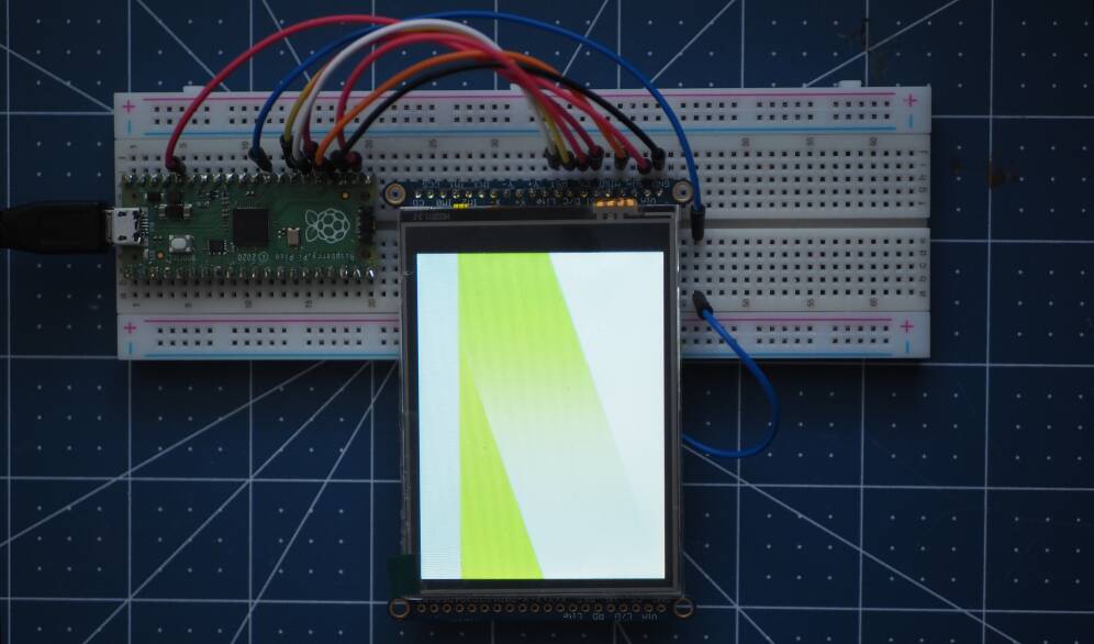
In typical use cases, small sections of the display are updated at a time. In my case, however, since I intend to have full screen scrolling with fancy animation, this wasn't going to cut it. As such, I took two major steps to improve performance.
The first, and probably the simplest, was maxing out the SPI interface's frequency. This provided some marginal improvements to the frame-rate, but the screen tearing was persistent.
The second approach, was switching to a multi-core architecture where one core of the pico was dedicated to pushing data to the display and the other was dedicated to writing to a display buffer. Even with this, there was still practically no improvement.
At a point, I was of the view that my multi-core approach was flawed (and it could still be,) but when I consider the speed of the RP2040's SPI interface and the amount of data it needs to push if screen updates were not to be missed, I could tell the problem was definitely from the SPI's speed.
I didn't give up, though. After a little Internet sleuthing, I found out that the tearing in the display occurred because I was writing to the display buffer right around the time the display controller was also reading the buffer. There was essentially no synchronization between my write operation and the controllers's internal read operation. As such, the controller could be reading data from the middle of the screen, while I will be writing somewhere at the beginning, causing two halves of different frames to be displayed at once, with the frames joined at the tear.
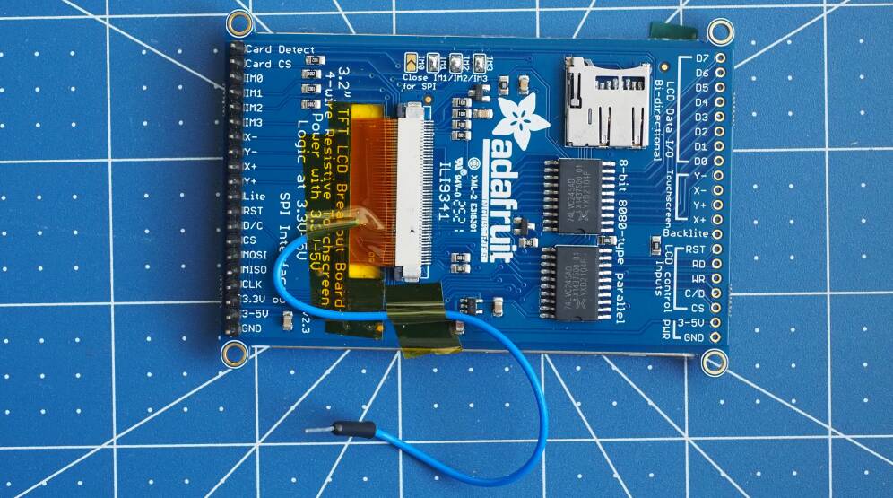
Fortunately, the display has a special pin—aptly named the Tearing Effect (TE) pin—which signals a good period within which to write data. Whenever this pin is high, data could be written to the display with the guarantee that it's not being read simultaneously. Unfortunately for me, though, the Adafruit breakout board didn't expose this pin. I went ahead and painfully soldered one on, anyway. But that didn't help either. Although the pin was correctly doing its job, the Pico was still too slow to write within the allotted time.
Conclusions and Next Steps
It became obvious the serial interface may not be the way to go. If my goal was to push more data to the display, I needed to go parallel. My conclusion may still be wrong, and the problem may be with my implementaion, but I'll never know if I don't try.
As it stands, the Adafruit break-out board I have exposes only eight of the display's parallel pins. And to use them I need to physically solder a jumper on the board. Since I really want max performance, I'll ultimately be looking at making my own breakout board which exposes all 18 parallel lines. In the meantime, however, I'll see how much improvement I could get from the 8 bit parallel interface. This will definitely be a huge undertaking, but I'm here for the challenge.